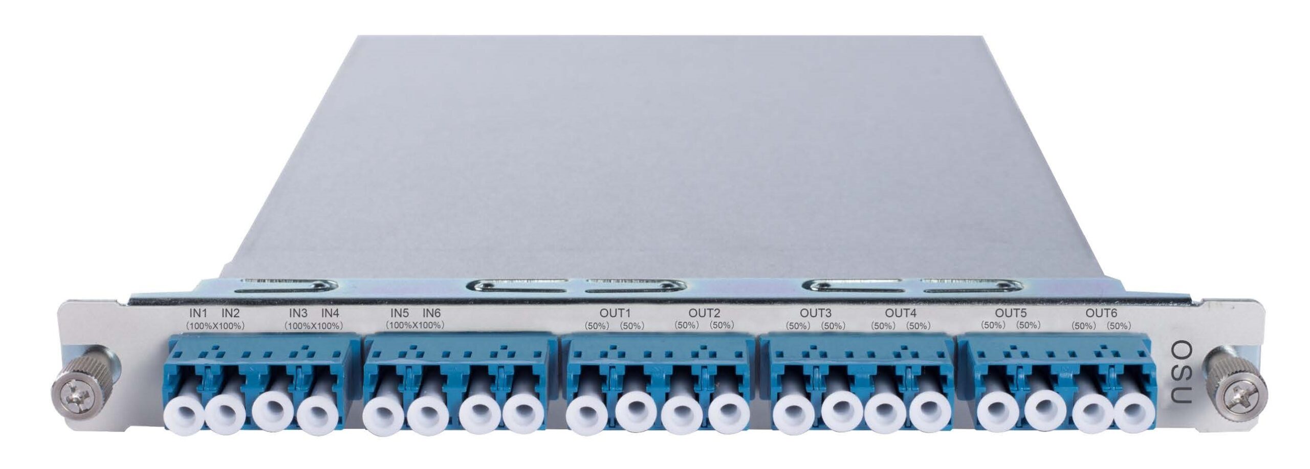
Optical splitter units are crucial for distributing optical signals in communication networks. They support both single-mode and multi-mode applications, providing versatility in network design. The splitters ensure low insertion loss and low polarization-dependent loss, maintaining high-quality signal transmission. Their passive design operates without the need for external power, offering a reliable and cost-effective solution for signal distribution.
Description
Optical Splitter Units (OSU)
The optical splitter units utilize PLC and FBT technology to split optical signals in communication networks, ensuring efficient distribution of signals across multiple output ports.
Description
The OSU optical splitter device is based on PLC (Planar Lightwave Circuit) and FBT (Fused Biconical Taper) technology. It is mainly used for communication trunk lines, metropolitan area networks (MAN), local area networks (LAN), private networks, DPI, and PON’s FTTX. Our company’s 1N and 2N PLC and FBT splitters are compact and cost-effective, supporting a wide wavelength range (1260nm-1620nm), providing customers with low insertion loss and low polarization-dependent loss.
Features
- Wide Wavelength Range: Supports single-mode and multi-mode applications, ensuring compatibility with various network setups. This wide range enhances the splitters’ versatility and application scope.
- Low Insertion Loss: Ensures minimal signal loss during splitting, maintaining signal integrity. This low loss is crucial for high-quality transmission.
- Low Polarization Dependent Loss: Provides consistent performance regardless of the polarization state of the light, ensuring reliable signal transmission. This feature enhances overall network performance.
- Transparent Transmission: Operates without the need for external power, providing a reliable passive solution. This transparency simplifies network design and reduces operational costs.
- Compact Design: Easy to install and maintain in various network environments, simplifying network management and minimizing space requirements. This compact design ensures efficient network operation.
| Parameter | Technical Indicators |
|---|---|
| Wavelength Range | Single-mode: 1260nm~1650nm<br>Multi-mode: 850nm |
| Insertion Loss | 1:2 (Equal Split)<br>Single-mode: 50%: ≤3.50dB<br>Multi-mode: 50%: ≤4.10dB |
| 1:3 (Equal Split)<br>Single-mode: 33.3%: ≤5.40dB<br>Multi-mode: 33.3%: ≤5.80dB | |
| 1:4 (Equal Split)<br>Single-mode: 25%: ≤7.00dB<br>Multi-mode: 25%: ≤7.60dB | |
| 1:8 (Equal Split)<br>Single-mode: 12.5%: ≤10.30dB<br>Multi-mode: 12.5%: ≤11.10dB | |
| 1:16 (Equal Split)<br>Single-mode: 6.25%: ≤13.50dB<br>Multi-mode: 6.25%: ≤14.20dB | |
| 1:32 (Equal Split)<br>Single-mode: 3.125%: ≤17.00dB<br>Multi-mode: 3.125%: ≤17.70dB | |
| 1:64 (Equal Split)<br>Single-mode: 1.563%: ≤20.50dB<br>Multi-mode: 1.563%: ≤21.20dB | |
| 60:40 Split<br>Single-mode: 60%: ≤2.70 dB / 40%: ≤4.70dB<br>Multi-mode: 60%: ≤3.20 dB / 40%: ≤5.20dB | |
| 70:30 Split<br>Single-mode: 70%: ≤1.90 dB / 30%: ≤6.00dB<br>Multi-mode: 70%: ≤2.50dB / 30%: ≤6.50dB | |
| 80:20 Split<br>Single-mode: 80%: ≤1.20 dB / 20%: ≤7.90dB<br>Multi-mode: 80%: ≤1.40dB / 20%: ≤9.00dB | |
| 90:10 Split<br>Single-mode: 90%: ≤0.80dB / 10%: ≤11.60dB<br>Multi-mode: 90%: ≤1.30 dB / 10%: ≤12.00dB | |
| 70:15:15 Split<br>Single-mode: 70%: ≤1.90dB / 15%: ≤9.00dB<br>Multi-mode: 70%: ≤2.50dB / 15%: ≤10.50dB | |
| 80:10:10 Split<br>Single-mode: 80%: ≤1.20dB / 10%: ≤11.60dB<br>Multi-mode: 80%: ≤1.20dB / 10%: ≤12.00dB | |
| 70:10:10:10 Split<br>Single-mode: 70%: ≤1.90dB / 10%: ≤11.60dB<br>Multi-mode: 70%: ≤2.50dB / 10%: ≤12.00dB | |
| 60:20:10:10 Split<br>Single-mode: 60%: ≤2.70dB / 20%: ≤7.90dB / 10%: ≤11.60dB<br>Multi-mode: 60%: ≤3.20dB / 20%: ≤9.00dB / 10%: ≤12.00dB | |
| Polarization Dependent Loss (PDL) | ≤0.15dB |
| Return Loss | ≥55dB |
| Directivity | ≥55dB |
| Dimensions (Single Board) | 177 (W) × 20 (H) × 225 (D) (mm) |
| Dimensions (Single Chassis) | 440 (W) × 44 (H) × 220 (D) (mm) |
| Operating Temperature | -10℃ ~ 50℃ |
| Storage Temperature | -40℃ ~ 80℃ |
| Relative Humidity | 5% ~ 95% non-condensing |
| Safety & EMC Compliance | FCC, UL, CE, TUV, CSA standards |
Classic Networking Applications
The optical multiplexer and demultiplexer equipment are widely used to address the issue of insufficient optical cable resources in transmission. Using Thin Film Filter (TFF) technology and Planar Lightwave Circuit (PLC) technology, multiple optical carrier signals are multiplexed onto a single optical fiber for transparent transmission. This supports dual-fiber bidirectional, single-fiber bidirectional, and single-fiber single-direction applications.Application 1: Dual-Fiber Bidirectional Multiple optical carrier signals are multiplexed onto two-core optical fiber for transmission, utilizing the two-core optical fiber to transmit multiple services, significantly reducing investment costs and saving time in optical cable deployment.

Application 2: Single-Fiber Bidirectional Using the reversible property of light, multiple optical carrier signals are multiplexed onto a single-core optical fiber for transmission, utilizing the single-core optical fiber to transmit multiple services, significantly reducing investment costs and saving time in optical cable deployment.

Application 3: Smooth Upgrade Smooth upgrade involves connecting another multiplexer/demultiplexer through the expansion interface in the original wavelength division system to achieve smooth upgrade and expansion without affecting the original services.


